
香港城大《Acta Materialia》:新突破!通過觸發元素晶界異常偏析成功克服合金的氫脆行為
2022-10-08 15:59:14
作者:材料學網 來源:材料學網
分享至:


一個多世紀前,普遍存在的元素氫被發現對許多金屬材料有害,因為它會導致機械性能的嚴重降低,例如延展性、韌性和疲勞壽命,即氫脆(HE)。因此,HE在許多工業應用中都是一個關鍵問題,并吸引了廣泛的研究。最近,利用低溫轉移原子探針層析技術表征氫在金屬材料中的分布已取得進展。它證實了多晶合金中不可避免地存在的晶界(GBs)是氫積聚的優先位置,因為它們具有高過量自由體積。高濃度的H原子通過增強應變局部化、穩定空位、加速空穴萌生和聚結來加速GBs的脫粘,最終導致塑性有限的脆性晶間裂紋。因此,GBs對于多晶材料的抗氫脆能力起到至關重要的作用。
值得注意的是,GBs的化學環境會嚴重影響多晶材料的抗斷裂性能。近年來,高/中熵(HEA/MEA)合金引起了相當大的關注。HEAs/MEA的成分復雜性為調節GBs的局部化學環境和HE抗性提供了廣闊的空間。多項研究表明,面心立方(fcc)HEAs/MEA,如CoNiV、CoCrFeNiMn和FeCoCrNi合金,比某些商業合金,如奧氏體304不銹鋼(SS)更耐HE。HEAs/MEA的優異抗氫脆能力可能歸因于其低氫擴散率、高斷裂自由能和低不穩定層錯能量等因素。然而,盡管由于MEAs/HEAs的多組分特征,GB附近的化學分離經常發生,但很少有人研究GBs的局部化學對MEAs/HEAs耐HE性的影響。例如,據報道,鎳和錳可以在等原子CoCrFeNiMn HEA中以一般高角度共分離GBs,這可能會極大地影響它們的抗氫脆能力,但它們之間的相互作用和內在機制一直沒有得到很好的研究。
為此,香港城市大學材料科學與工程系楊濤教授領銜的研究團隊在其最新的研究成果中成功地揭示了FeCrNiCr高熵合金中抑制其氫脆行為的關鍵因素。研究發現,通過控制Fe元素地添加可以非常有效地觸發Cr元素在晶界(GBs)的局部偏析,從而可以有效消除Fex(CrCoNi)1-x面心立方(fcc)高熵合金(HEA)中長期存在的氫脆問題。結果表明,將Fe濃度從2.5增加到25 at.%導致HE阻力大幅提高,即延性損失從70%降至6%。同時,斷裂模式由沿晶斷裂轉變為穿晶斷裂。多尺度顯微結構分析表明,Fe2.5Cr32.5Co32.5Ni32.5和Fe25Cr25Co25Ni25合金在相結構、晶粒尺寸和晶界(GB)特征方面的差異可以忽略不計。然而,非常有趣的是,近原子分辨率元素映射顯示,Fe濃度的增加促進了GBs處的納米級Cr偏析,這主要是由Cr和Fe之間的強斥力和Cr的低自結合能引起的。這種Cr元素的異常界面偏析以前在Fe25Cr25Co25Ni25合金中沒有報道過,有助于增強GBs的內聚強度,并抑制GBs因GB能量減少而產生的局部氫偏析,從而導致顯著的HE抗性。這些發現揭示了當前FeCrCoNi型HEA中HE抗性大幅提高的根源,同時,為未來開發新型高性能結構合金提供了新的見解,該合金對氫致損傷具有非凡的免疫力。相關成果以“Defeating hydrogen-induced grain-boundary embrittlement via triggering unusual interfacial segregation in FeCrCoNi-type high-entropy alloys”為題,于2022年10月2日發表在國際知名材料期刊《Acta Materialia》上。
該論文的第一作者為香港城市大學材料科學與工程系的李倩。 其他主要合作者包括美國田納西大學的P.K. Liaw教授,哈爾濱工業大學(深圳)W.H. Liu教授 (共同通訊),香港城市大學S.J. Zhao教授(共同通訊);哈爾濱工業大學(深圳)Y.L. Zhao教授等。該研究受到了香港研究資助局(NSFC),國家自然科學基金(NSFC)、廣東省科技廳等項目的支持。
論文鏈接:https://doi.org/10.1016/j.actamat.2022.118410 。
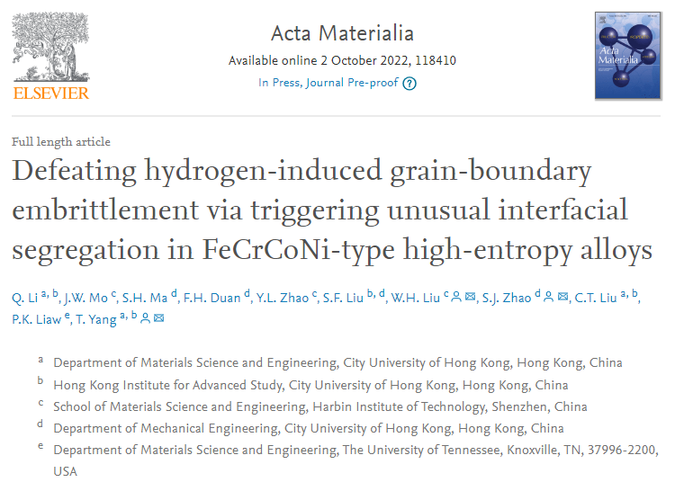
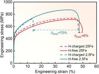
Fig.1. Engineering stress-strain curves of the 2.5Fe and 25Fe alloys in the hydrogen (H)-charged and -free states.
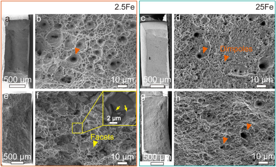
Fig. 3. Fracture surfaces of (a, b, e, and f) the 2.5Fe and (c, d, g, and h) 25Fe alloys in (a-d) the H-free and (e-h) H-charged states. The H-charged 2.5Fe alloy shows an intergranular fracture morphology with facets (marked with yellow triangles). Grain-boundary triple junctions (marked with yellow arrows) can be clearly observed on the magnification image (the top-right inset) of the region in the yellow box. The H-charged 25Fe samples show ductile fracture morphologies with typical dimples (marked with orange triangles).
Fig. 4. Microstructures of the as-annealed 2.5Fe and 25Fe alloys. (a) X-ray patterns of the H-free/-charged 2.5Fe and 25Fe alloys, and inverse pole figure (IPF) maps of (b) the H-free 2.5Fe and (c) H-free 25Fe alloys showing the single fcc phase recrystallized microstructures. (d) A bright-field TEM image and (e) a high-resolution TEM image of the H-free 25Fe alloy presenting the single-fcc structure without the formation of other precipitates. (f) The EDS maps of the regions in the H-free 25Fe alloy exhibiting the homogeneous elemental distribution in the grain interior.
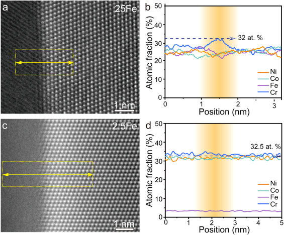
Fig. 5. High-angle annular dark-field (HAADF) images of GBs in (a) the H-free 25Fe and (c) H-free 2.5Fe alloys, and (b, d) the corresponding elements profiles across GBs.
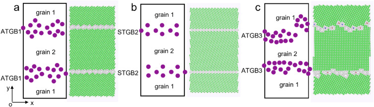
Fig. 6. Schematic of GB Structures. The GB configurations for (a) the GB1 (asymmetric tilt GB, ATGB, Σ13{320}), (b) GB2 (symmetrical tilt GB, STGB, Σ11{332}); and (c) GB3 (ATGB, Σ13{100}).
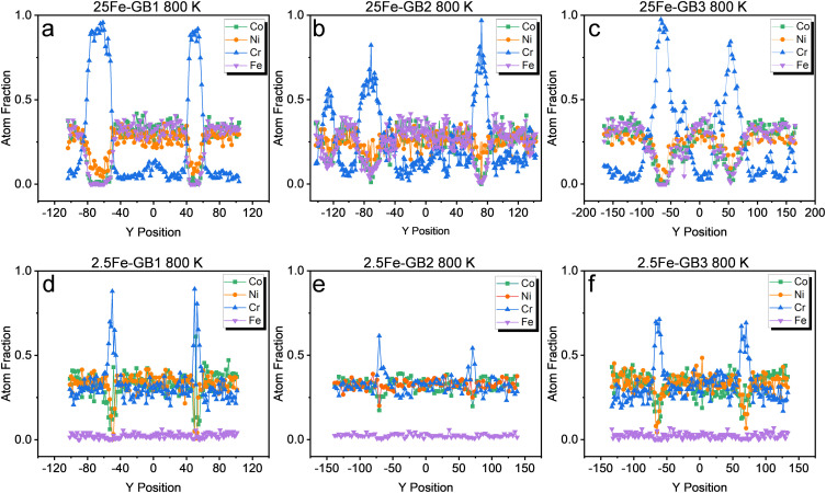
Fig. 7. The composition profiles across the computational systems along the Y direction after MC/MD at 800K for (a, d) GB1, (b, c) GB2, and (c, f) GB3 in (a-c) the 25Fe and (d-f) 2.5Fe alloys.
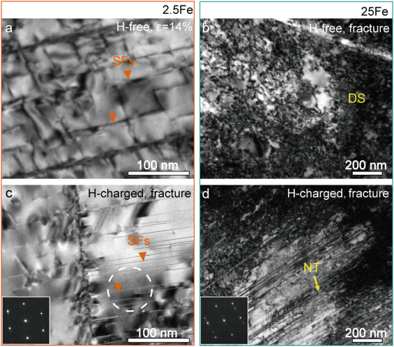
Fig. 11. Typical bright-field TEM images of (a) the H-free and (c) H-charged 2.5Fe alloy deformed with the engineering strain of ε = 14% (the H-charged 2.5Fe alloy failed at the strain ε = 14%); and the fractured microstructure of the 25Fe alloy (b) without and with (d) hydrogen charging. (DS: Dislocation structure, NT: Nanotwin, SFs: Stacking faults)
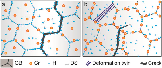
Fig. 12. Schematics illustrating the HE mechanism of (a) the 2.5Fe and (b) the 25Fe alloys.
免責聲明:本網站所轉載的文字、圖片與視頻資料版權歸原創作者所有,如果涉及侵權,請第一時間聯系本網刪除。
相關文章

官方微信
《腐蝕與防護網電子期刊》征訂啟事
- 投稿聯系:編輯部
- 電話:010-62316606-806
- 郵箱:fsfhzy666@163.com
- 腐蝕與防護網官方QQ群:140808414
點擊排行
PPT新聞
“海洋金屬”——鈦合金在艦船的
點擊數:8188
腐蝕與“海上絲綢之路”
點擊數:6503